- Do I really need to read this? - A recent
question was:
"...But do I really have to fuss with additives and titrations of kerosene and fret about cloud points and wax crystals and de-gunking my intercooler? Don't get me wrong, all that jazz is absolutely engaging and fascinating to my scientific mind, but in a conceptual and theoretical way; not one I actually want to get my hands dirty over (literally and figuratively)." -(Victoria, Jan. 2000).
The answer is yes and no. This stuff is good to know and well worth the time to learn more usable knowledge. If this really isn't what you want, Peter Cheuk had some good advice:"
"One thing to keep in mind about these forums is that we are enthusiasts. Some of us are overzealous when it comes to our cars. Some of us are anal retentive . We maintain our cars better than we do our personal relationships (my wife suggested I sleep with the car a few times). I honestly think that the car can be treated like a gasoline car in most respects with the exception of pumping diesel instead of gas. Oil changes at the factory recommended 10,000 miles with synthetic oil and changing the fuel and air filters at 20,000 miles are the only maintainance that you will need to do until you need to have the timing belt changed. If you compare this engine to the darling of VW's fleet, the 1.8T, you will see that the TDI is cheaper and simpler to maintain, not to mention the economy of operation. I've done just that. "
So read on, expand your mind. You don't have to become a "motor head", but if you hang around with us too long you might just become one. - VW
Derf
- VW
Derf
- General - The TDI engine is a turbocharged
and intercooled diesel engine with "direct injection" -
that is, the fuel injector nozzle sprays directly into the main combustion
chamber, rather than into a separate prechamber as was done with previous
automotive diesel engines. This is similar to the way that bigger
diesel engines have worked for many years, but with countless improvements
to refine the process and make it suitable for a passenger car engine.
The result is an engine which is so refined in comparison to older
passenger car diesel engines, that there really is no comparison.
Back to Top
- Improvements over Previous Diesels - The
TDI engine, compared with previous diesels from Volkswagen and others,
offers the following benefits.
Electronic control of the fuel injection system means more power, less smoke, less noise, and even better fuel consumption. Both injection timing and quantity are electronically controlled on all Volkswagen TDI engines. Previous Volkswagen diesels have used mechanical regulation of the fuel injection system. The "cold start" handle familiar to drivers of older VW diesels has been eliminated, and the function that it served is now handled automatically by the engine controller.
Developments in turbocharger technology have culminated in the Garret VNT15 variable-geometry turbocharger on the latest 4-cylinder TDI models. This design gives faster response (less "lag" - although this was minimal even on the older models), and is capable of delivering boost starting at a lower engine speed and extending to a higher engine speed with less back-pressure of the exhaust flow. Turbo lag with the VW TDI engine is on the order of 0.25 second, which is not noticeable to the driver.
Electronically controlled emission control systems, including EGR (exhaust gas recirculation), reduce emissions of nitrogen oxides (NOx). Previous VW diesels did not include this function because the mechanical controls were not capable of providing adequate control.
Higher injection pressures and developments of fuel injector design mean less noise and lower exhaust emissions. Two-stage injector nozzles are used, to give a gradual pressure rise and minimize the diesel "knocking" sound.
The open-type combustion chamber has less heat loss than the older prechamber design. As a result, there is no need for glow plug operation at coolant temperatures above 9 degrees C, so starting can be immediate. In addition, there is no need for an engine block heater, which was an essential option for anyone with an older-design diesel in a cold climate.
Updated glow plug design compared to previous models reduces the glow period to about 10 seconds even at -10 degrees C.
The open combustion chamber allows the use of a lower compression ratio (18.5:1 or 19.5:1 depending on model, compared to about 22:1 or 23:1 on older designs). This reduces noise and vibration, and increases engine durability since the maximum pressure in the combustion chamber is reduced.
Back to Top
- Fuel System - The features, components,
and operation of the fuel system are as follows:
The fuel tank is made of plastic to eliminate any chance of corrosion, and is located under the floor in the area below the rear seat. There is an access cover to the top of the tank, held by three screws, under the right rear seat. This provides access to the "dip-tube" and level sensor sender unit It appears removable/replaceable without having to remove the tank. In the filler neck of the tank, in the 9 o'clock position is a little black button. This is a vent relief valve that can be pushed with the fuel nozzle when "topping up" the tank to squeeze in a few extra litres. The button is normally activated when the fuel cap is screwed on.
It should be noted that the vent valve is to prevent topping up. Overfilling the tank could cause heat expansion to push fuel up the neck and create a spill. The vent keeps an amount of air in the tank until the cap is returned. The air in the tank moves up into the neck as the fuel in the neck moves down into the tank. Any expansion could now burp air instead of fuel. Topping up using the vent valve should be done only when the car will be driven long enough to consume a few litres of fuel before stopping the engine. Don't top off with the vent pressed and then park in the sun. For accurate fuel mileage calculations always use the same technique when refueling Either always "top up" by venting the expansion chamber, or never vent and stop refilling when the dispensing nozzle shuts off. That extra half gallon or two liters of fuel squeezed into the expansion chamber will make the trip consumption appear higher if this venting technique is used intermittently.
The fuel lines take fuel to and from the tank. These are two plastic lines, divided into approximately three sections each, running under the body of the car from the tank to engine compartment. Fuel is drawn from the tank through a suction line under the car, and into the fuel filter/water separator, which is located within the engine compartment. (Unlike with gasoline engines, there is no tank-mounted electric pump, and the low volatility of diesel fuel eliminates the need for any evaporative emission control components, thus simplifying the fuel system.) The fuel line sections attach to each other with "quick connect/disconnect" joints. Joints can be undone by pressing a small slim button on the joint itself. Joints are also potential places for leaks. The delivery line is colored all black and the return line is blue, but some pieces have simply a blue stripe painted on.
In the engine compartment, both lines attach to the fuel filter. The purpose of the fuel filter is to remove suspended particles of debris and water from the fuel supply. The entire filter should be replaced periodically, according to the maintenance schedule for your vehicle.
The supply line provides raw fuel from the tank to the input nipple of the filter. Filtered fuel is drawn by the injector pump from the output nipple via the clear section "sight-tube" line, visible by lifting the hood, between the fuel filter and the engine cover. The return line from the injector pump is also attached to the top of the filter via an inline "tee-piece", held in place on the filter by a spring clip. The tee-piece is a temperature sensitive valve that opens when the fuel temperature is below about 15 C / 60 F, and closes fully when above 25 C / 80 F - the purpose of this is to supply some heat to the filter during cold conditions, to resist the tendency for cold diesel fuel to "gel".
The flow path for fuel is modified at lower temperatures. The valve in the tee-piece of the return line opens, and some of the excess (and warm) fuel flows back into the filter, instead of returning to the tank. While this valve is open, a "rattling" noise, like bb's in a salt shaker, may be heard from the fuel filter. At very low temperatures, only the net fuel consumed by the engine is drawn from the tank. This has the effect of quickly warming, and hopefully un-gelling, the supply of fuel in the filter first. As this fuel warms the valve closes, and warm fuel is sent down the return line in exchange for cold (and possibly quite sluggish) fuel from the tank. In this way fuel in the tank is gradually un-gelled and warmed up.
Fuel is then drawn through a clear plastic hose from the fuel filter and into the fuel injection pump. There are three types of fuel injection systems currently in production, depending on the model, which will be discussed below. The pump delivers fuel in sequence to the injector nozzles under high pressure (900 bar or 13,500 psi on older models, even higher on newer models), and timed so that the injection event occurs in the vicinity of the end of the compression stroke. Injection timing and quantity are both controlled accurately by the engine controls, discussed in a later section. Excess fuel which is pumped into the injection system but not delivered to the engine at that time is returned to the tank through a separate line. In cold weather, this hot return fluid passes through the fuel filter as described above.
Most VW TDI models, including all sold in North America, use an electronically controlled Bosch VP 37 distributor-type injection pump which is mounted on the front of the engine and driven by the timing belt. This delivers fuel to separate injectors at each cylinder through high-pressure steel fuel lines. This system is used on the 1.9 litre 4-cylinder engines of both 90hp and 110hp, and is also used on the 2.5 litre 5-cylinder engine as well as the 2.5 litre V6 of 150hp. The latter engines have the injection pump mounted elsewhere on the engine but they work the same way. Inside the distributor-type pump, fuel is first drawn into a vane pump which pressurizes the pump housing to a low pressure, which is below the injection pressure. A single plunger rotates together with the input shaft but is also spring-loaded against a cam, so that the plunger moves in and out of a cylinder with ports in it. When the plunger is pulled back, fuel enters the cylinder via the fuel cutoff solenoid valve which is visible on top of the pump housing with a single wire going to it. When the plunger advances (4 times per plunger revolution in the case of a 4-cylinder engine), fuel is delivered through a passage in the plunger to whichever fuel line aligns with a port in the rotating plunger, thus fuel is delivered to the appropriate cylinders in sequence. Eventually, on each stroke, the plunger advances far enough that another port in the plunger is uncovered by the cutoff sleeve and any remaining fuel behind the plunger is bypassed rather than being injected into the cylinders. This sleeve is positioned in and out along the plunger so as to vary the quantity of fuel being injected, as directed by the engine controls. Injection timing is varied by rotating the cam profile that the plunger is pressed against; this is done by a small hydraulic cylinder controlled by a solenoid valve located on the bottom of the injection pump housing. Excess fuel which is not delivered to the engine is returned to the fuel tank through a return line.
Each injector contains a spring-loaded plunger which opens when the fuel pressure reaches a certain amount. The plunger then uncovers 5 injection orifices of extremely small diameter. The preload springs operate in two stages so that the initial injection occurs at a lower pressure, followed by the main part of the fuel at a higher pressure. This results in the fuel igniting progressively, thus reducing the noise level of the engine.
One of the improvements made on the A4 engines compared to previous models involved the increased fuel injection pressure from the injection pump with optimization of the fuel injectors. Manual transmission A4 TDI's have 800 bar (11,760 PSI) pump side pressure with 1100 bar (16,170 PSI) injection nozzle pressure. Automatic transmission A4 engines have 950 bar (13,965 PSI) pump side pressure with 1350 bar (19,845 PSI) injection nozzle pressure. To achieve this increase in pump and injection nozzle output pressures in the automatic transmission engines, the single injection pump plunger on the BOSCH pump was changed from 10mm to 11mm. This was required for emission purposes allowing the automatic version to inject the required quantity in the very limited time available at higher pressure, with a resulting 20% reduction in particulate emissions.
Other VW TDI models with the 1.9 litre 4-cylinder of 115 hp or 150 hp, and the 1.2 litre and 1.4 litre 3-cylinder engines, use a so-called "pumpe-deuse" (German) or "pump-nozzle" (English translation) system. In these engines, each cylinder has its own small high-pressure fuel pump which is actuated by the same camshaft that operates the intake and exhaust valves. Fuel is delivered to each pump-nozzle by a low-pressure pump serving the same function as the internal vane pump in the distributor-type system. As the engine cylinder approaches the end of the compression stroke, the main pump plunger advances, pressurizing the fuel. A solenoid valve adjacent to each pump-nozzle is normally open and bypasses the fuel. When the solenoid valve is energized, the bypass passage is closed and the fuel is forced to an extremely high pressure and through the injection nozzle. At the end of the required injection period, the solenoid valve de-energizes and any remaining fuel pumped by the plunger bypasses the nozzle. Thus, fuel is injected as long as the solenoid is energized, allowing full control of injection timing and duration. This system has the significant advantage of eliminating the separate high-pressure fuel lines from the pump to the nozzle because it is all built into a single unit, thus giving better control of the injection cycle.
Finally, some modern diesel engines use a "common rail" injection system. The concept is much like a conventional gasoline engine EFI system but the pressure involved is on the order of 1000 times higher. A single central high-pressure pump delivers fuel to a pressurized fuel line, and separate solenoid valves on each cylinder admit fuel into each injector. Although this sounds simple, it is extremely difficult to make it work due to the extremely high pressures involved. This system is used on the 180hp version of the 2.5 litre V6, and on the 3.3 litre V8.
Back to Top
- Air Intake System, EGR, PCV - Air is drawn
through a conventional air filter and into the so-called MAF, or mass-air-flow
meter. A hot wire (older models) or hot film (later models) is contained
inside this sensor and is maintained at a constant temperature.
The electrical current which is required to maintain this temperature
is an indication of how much airflow is passing over the sensing element.
After the MAF, a hose connection comes from the valve cover where
crankcase fumes are drawn into the intake air. From there, the intake
air is drawn into the compressor of the turbocharger (see below) where
it is compressed, but the compression process also increases the temperature
of the air. The hot compressed air passes through a small heat exchanger
known as the intercooler. When heat is removed, the density of the
air increases, thus increasing the amount (by mass) of air which is
drawn into theengine. The objective is to make the air going into
the engine cylinders as dense as possible (pressurized and cooled)
to allow maximum power output. From the intercooler, the pressurized
and cooled air goes to the intake manifold where it is mixed with
a proportion of exhaust from the EGR (exhaust gas recirculation) system
for emission control purposes. (The EGR system is connected on the
high-pressure side of both the exhaust and intake systems.) This mixture
then goes into the engine cylinders. Unlike with a gasoline engine,
there is no throttle in a diesel engine. Power output is governed
using the fuel supply only. The lean air/fuel mixture is one of the
reasons that the diesel engine is so efficient, and the lack of intake
restriction due to absence of a throttle reduces pumping losses, and
that is another reason that a diesel engine is more efficient when
running under part load. The A4 engines have an added intake manifold
flap to reduce shudder and compression pressures on diesel shutdown.
Previous A3 TDI's did not have this feature.
Back to Top
- Engine - The 4-cylinder engine uses a cast-iron
block and an aluminum head with 2 valves per cylinder. Some newer
designs (like the V6 model) use 4 valves per cylinder. Whereas gasoline
engines use 4 valves per cylinder for better breathing at high engine
speed, this is of little benefit to diesels. The main benefit of using
4 valves per cylinder in a diesel engine is to allow the injection
nozzle to be located precisely in the center of the combustion chamber
and mounted vertically - this gives better fuel distribution within
the combustion chamber, hence more power and lower exhaust emissions.
The displacement of all 4-cylinder models is 1.9L, 1896cc or 115.7
cubic inches. The bore (79.5mm) and the stroke (95.5mm) is the same
on the A3 and A4 models. The compression ratio is 19.5:1 on the 90hp
and 110hp models, and reduced to 18.5:1 on the 115hp model. The new
engine used in the A4 models features a cast iron cylinder block,
light alloy cylinder head and aluminum oil and a magnesium
cylinder head cover. It also has the same piston oil spray nozzles
as the earlier A3 TDI engines which spray oil against the bottoms
of the pistons for added cooling. Both A3 and A4 engines have 5 main
bearings on the crankshaft. Both the A3 and A4 engines have a single
overhead camshaft driven by a toothed belt with semi-automatic belt
tensioner. Both engines enjoy lightweight valve train with 2 valves
per cylinder and reinforced exhaust valves for high temperature resistance.
Both engines are transversely mounted with the new A4 engine featuring
the new improved "Pendulum" type engine mounts for increased
smoothness and freedom from vibration. The new A4 engine has a chain
driven internal gear oil pump driven from the front of the crankshaft.
The new A4 engine now has a camshaft driven vacuum pump. The A3 engine
as a spin on cartridge oil filter down below the engine assembly next
to the oil pan while the newer A4 version has a drop-in cartridge-type
oil filter accessible from the top front of the engine bay. Both TDI
models have radiator cooling added to their EGR valves to reduce the
temperature of the EGR gases approximately 122 degrees Fahrenheit
resulting in a 15% decrease in NOx emissions.
The use of a belt-drive for the camshaft on a diesel engine has been the subject of some criticism, because camshaft timing belts generally fail with no warning, and this failure has tremendous consequences. If this ever happens, the camshaft will stop immediately, while the crankshaft and pistons will keep going, driven forward by the still-moving car and still-turning drivetrain. It's guaranteed that the camshaft will stop with some valves open, and a piston will hit a valve ... crunch ... this leads to many expensive broken parts inside the engine. It is therefore crucial that the timing belt be replaced in accordance with the maintenance schedule! It should also be replaced any time there is doubt as to its condition, such as if an oil or fuel leak causes these fluids to contaminate the belt.
Gasoline engines can be designed so that even if the timing belt breaks, the valves will not contact the pistons, regardless of what position the camshaft stops in (a so-called non-interference engine). Not all gasoline engines are non-interference ... but they can be. This is impossible with a diesel engine because of the high compression ratio, and the small space between the piston and head in order to achieve that compression ratio. All 4-stroke diesel engines are therefore interference designs.
The new A4 engine has reduced crevice volume in the combustion chamber achieved with a new piston design. The new piston design has the top ring being moved to within 6mm of the piston crown, up from the previous 9mm of the A3 engines. This is a critical area of diesel piston design and assists in lowering the visible smoke output and the emissions through the oxidative 55mm catalytic convertor (A3 engines had 50mm oxidative catalytic convertors).
The A4 engine also enjoys a new oil pump, vacuum pump and water pump drive system with the elimination of the auxiliary drive shaft as found in earlier A3 engines. The familiar water pump thermostat housing that has been on the earlier VW 4-cylinder engine designs for the last 23 years is replaced with housings cast integral with the block and a plastic impeller pump. With the elimination of the intermediate shaft, the oil pump is moved up to the front of the engine and driven by chain from the crank. A spring loaded tensioner takes up any slack in the chain. The oil pump itself is a modern gerotor design, which pumps more oil using less power, has fewer moving parts and a smaller gear intermesh to minimize contact area and reduce friction. The modified oil circuit provides faster oil pressure build up, particularly during cold starts. The pressurized oil is controlled at the clean-oil end with the resulting faster build up of oil pressure which has a positive influence on less wear (shorter mixed friction time after starting). The vertical oil filter also assists with the ease of maintenance with a fully incineratable filter cartridge that is easy to access and easy to replace. A single oil pressure switch is used (the A3 models had two oil pressure switches, one high and one low) with an oil control valve mounted downstream of the oil filter. The new cylinder head cover also has an integrated oil separator to minimize oil consumption.
The new A4 engine also has a new lightweight cast aluminum oil pan using silicone sealant instead of a gasket on the previous A3 models. The oil pan is also bolted to the transmission housing to increase rigidity. The cylinder head cover is now cast in magnesium and uses a series of perimeter fasteners rather than the three center bolts on the A3 TDI design. There is no separate gasket on the cylinder head cover, instead the seal is bonded and positively located to give a more reliable seal. The wire mesh separator inside provides for better oil separation and increased crankcase breathing.
One of the biggest changes the A4 design includes is the new reinforced engine and transmission mount design, working on the principle of a pendulum. The engine is suspended from above on a bonded rubber transmission mount and rubber and hydraulically dampened motor mount, and located in the lower rear with a "pendulum support". This effectively dampens chassis shake, noise, vibration, and harshness and acts as a torque rod that reduces engine twist during hard acceleration. At rest, all three mounts are without any preload. Under acceleration or braking, the upper mounts twist while the lower pendulum mount dampens and restricts excessive movement.
Back to Top
- Turbocharger - The function of the turbocharger
is to increase the amount of air which enters the engine, thus allowing
the power and torque to be increased tremendously compared to an engine
without a turbocharger. It works rather like a miniature jet engine.
A turbine is located in the exhaust from the diesel engine, and converts
the pressure of the exhaust gases to mechanical work on a shaft. A
compressor wheel is driven by this shaft, and draws air from the air
intake, compresses it, and pressurizes the intake manifold of the
diesel engine. The shaft of the turbine and compressor is mechanically
independent of any connection to the rest of the engine - it spins
freely on its own. The bearing on this shaft is lubricated by engine
oil, fed by a separate oil line from the vicinity of the oil filter,
and the oil drains into the crankcase through a drain pipe. The oil
also serves to cool the turbine; there is no connection to the engine
coolant.
Conventional turbochargers have the advantage of recovering part of the exhaust energy to increase the power of the main engine, but the disadvantage that they only operate under optimum conditions at a single engine speed - which, in the case of the 1.9 4-cylinder, is about 2000 rpm. Below that speed, there is not enough energy contained in the exhaust gases to allow the design level of "boost" to be achieved. Above that speed, there is too much energy in the exhaust, and the turbine tends to overspeed and generate too much boost. There are various ways of dealing with this - some models use a so-called "wastegate" which is the original design, and other models use a set of vanes in the turbine section to vary the angle and speed that the exhaust gases strike the turbine.The A3 90hp engines use a conventional Garrett GT15 turbocharger with an internal wastegate. When the engine speed is below the optimum design speed for the turbo, the turbo does whatever it can, and the engine gets less boost than design ... nothing can be done about it. As engine speed increases, the boost level also increases because the extra exhaust energy spins the turbine faster. When the boost level starts to exceed a certain amount, the engine controls supply pressure to the wastegate actuator, which then bypasses part of the exhaust around the turbine. This causes less energy to be delivered to the turbine, so the boost level drops, and the engine controls operate so as to keep the boost level at the design level.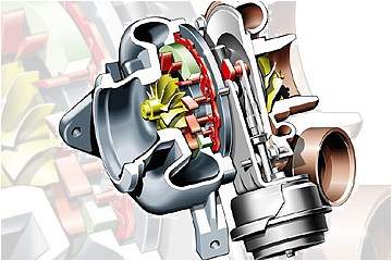
To improve performance in "off-design" conditions, the A4 engines (and the A3 110hp engines) use a variable-geometry Garret VNT15 turbocharger. There is no wastegate, and all of the engine exhaust passes through the turbine all the time. When the engine is running slowly, a set of vanes inside the turbine housing move, to direct the exhaust gases through the turbine at a shallower angle but a higher speed; this causes the turbine to spin faster, so that the turbo compressor can reach the design boost level sooner. As the engine runs faster and the amount of exhaust gases increase, the boost level starts going up; this is detected by the engine controls which act to move the vanes toward a more open angle. This allows less energy to be transmitted to the turbine wheel, so the boost level is reduced. Compared with the previous design, this arrangement allows the design boost level to be developed faster and at lower engine speeds, and allows more efficient operation with reduced exhaust back pressure at higher engine speeds.
Another design change with the new A4 engines is that the turbine housing is built into the exhaust manifold instead of being a separate piece, thus eliminating a potential leakage point.
For the 90hp engines, typical boost level at full load is 15 to 16 psi intermittently and 12 to 13 psi continuously.Back to Top
- Engine Controls - All North American
models use BOSCH's Motronic 5.9.2 electronic engine management systems.
The TDI engine is a "drive by wire" design. There is no
mechanical connection between the accelerator pedal and anything else.
Pressing the accelerator pedal provides an input to the ECU (engine
computer) indicating that more power is desired. The ECU takes into
account accelerator pedal position and engine speed, then "decides"
how much fuel is being requested by the driver. It compares this request
with the signal from the MAF (airflow meter); if the MAF signal indicates
that for whatever reason there is not enough airflow for the requested
amount of fuel, the ECU cuts back the amount of fuel to prevent black
exhaust smoke from being emitted. It is worth noting that if
the accelerator and brake pedals are both depressed, the ECU detects
the condition and brings the engine to idle speed as a safety feature,
ignoring the accelerator input. (During "normal" driving
this presents no obstacle, but enthusiastic drivers who can do racing-style
"heel and toe" downshifts while braking may find that this
safety feature thwarts their attempt to "match revs"...)
The result of this calculation is the desired amount of fuel to be injected. Within the distributor-type injection pump is a small electric motor which positions the fuel cutoff sleeve around the injection plunger; this changes the effective stroke of the plunger and thus varies the amount of fuel being injected. A position feedback device measures the actual position of this cutoff sleeve, thus giving the ECU precise control of the fuel quantity.
It is also necessary for the ECU to vary the injection timing for the best compromise between power, economy, and emissions. Injection quantity and engine speed are taken into account to determine the desired start-of-injection timing. A sensor located on injector number 3 (that's why this injector is bigger than the others and has a wire to it), in conjunction with a position sensor near the engine flywheel, allows the actual timing of the start-of-injection to be measured by the ECU. The ECU compares the actual start-of-injection timing, to a calculation of where the timing should be. A solenoid on the injection pump is energized or de-energized, depending on whether the measured injection timing is too far advanced, or too far behind. This operates a small hydraulic cylinder, which shifts the cam that the injection pump plunger rides against, thus altering the injection timing under closed-loop control.
The engine control unit also is responsible for operating the exhaust-gas recirculation system. Diesel engines have no throttle plate to limit the amount of intake air. This means that more oxygen is in the cylinders than can be used during fuel combustion. The high temperatures in the cylinder can combine this excess oxygen with nitrogen to form oxides of nitrogen (NOx). Recirculating exhaust with its partially depleted oxygen level back into the intake air lowers the combustion temperatures making it less possible to produce high quantities of NOx. If the ECU program determines, based on coolant temperature, altitude, engine speed and other variables, that operating conditions could lead to production of high levels of NOx, the ECU operates a solenoid which applies vacuum to the EGR valve, causing it to open. This causes the combustion temperatures in the cylinders to be reduced since the exhaust gas has less oxygen than the displaced fresh intake air. If the ECU program determines that conditions do not favor production of NOx, then the ECU acts in the other direction and closes the EGR valve. Too high a combustion temperature leads to formation of NOx, too low leads to greater amounts of CO and "soot". The ECU regulates the EGR opening size to maintain this balance between too much and too little. On models equipped with the OBD-II system (i.e. North America), if the ECU cannot achieve the desired level of oxygen in the exhaust, the "check engine" light will come on.
The engine controls also operate the turbocharger, to regulate the boost pressure. On A3 models, a hose leads from the intake manifold to a pressure sensor located within the ECU. When the boost pressure exceeds a setpoint, a solenoid valve transmits boost pressure to the wastegate actuator, which then opens the wastegate, causing the boost pressure to come down - the control strategy is quite simple. On A4 models, the pressure sensor is located on the intake pipe coming from the intercooler. Control of the boost pressure is done by varying the position of vanes inside the turbocharger.
The glow plug system, used for cold starts, is also controlled by the ECU. When the "ignition" switch is turned "on" and the coolant temperature is below 9 degrees C, the glow plugs operate for a time which depends on the measured coolant temperature (i.e. about 10 seconds at -10 degrees C). The glow plug indication lamp on the instrument panel is an indication to the driver - "please wait". When this light goes off, the engine may be started. After it starts, the glow plugs operate for a period of time with the engine running, at engine speeds below 2500 rpm, in order to reduce emissions and improve engine operation during this time period. The glow plug indicator lamp does not operate during this stage.
In addition, some models have glow plugs in the coolant, to make the engine warm up faster, and to provide some heat to the passenger compartment sooner. These glow plugs operate for a period of time after the engine starts (without the glow plug indicator lamp).
Some may be under the impression that the glow plugs begin operating when the driver's door is opened. This is an "urban myth". The glow plugs do not operate until the key is turned "on".
All information Copyright © 1996-2002 Fred
Voglmaier.
All rights reserved. This FAQ (Frequently Asked Questions) may not be
reproduced without written permission.